In factories using Allen-Bradley CompactLogix control systems, the 1769-PB4 is a common DC power supply module. It is responsible for providing system power to the 1769 Compact I/O bus and related modules. When the control cabinet experiences module disconnection, I/O communication abnormalities, or the system fails to start normally, engineers often need to first confirm whether the power module is working properly.
However, a fault in 1769-PB4 does not necessarily mean that the module itself is damaged. Input voltage, module arrangement, current load, terminal connection, and field environment can all cause similar phenomena. Accurately identifying the cause before maintenance can reduce unnecessary replacements and downtime.
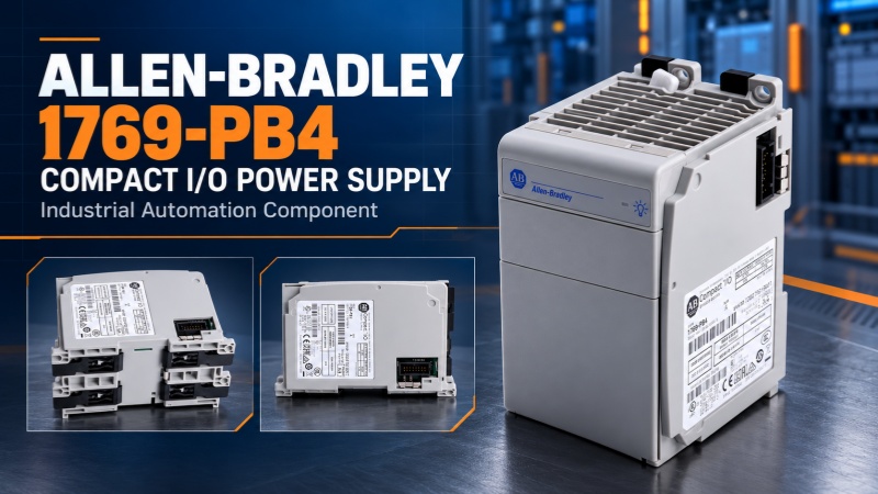
What is the basic function of the 1769-PB4?
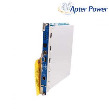
The 1769-PB4 is a DC power supply module from the Allen-Bradley CompactLogix family, designed for use with 1769 Compact I/O systems. According to Rockwell Automation product documentation, this model accepts a 24V DC input and provides 4A of 5V DC bus current, along with 2A of 24V DC bus current.
In a CompactLogix system, the controller and local I/O modules require a power supply configured according to the system's capacity. Additional I/O banks may also require their own dedicated 1769 power supply modules. Power capacity should not be determined solely by the number of modules; rather, it must be calculated based on the actual current requirements of each individual I/O module.
A key feature of the 1769-PB4 is its ability to distribute power to both the left and right sides. Official installation instructions state that this 4A-rated 1769 power supply module can provide up to 2A of 5V DC current to the right side and 2A of 5V DC current to the left side; for 24V DC, the distribution limit is 1A per side.
Therefore, even if the total rated capacity of the power supply module is not exceeded, an excessive local load on one side can still cause system instability.
Common Symptoms of Failure
When issues arise with the 1769-PB4, common field symptoms include:
- The controller fails to complete its startup sequence;
- Some 1769 I/O modules are not recognized;
- I/O status indicators display abnormal states;
- The controller reports communication or bus errors;
- The system experiences intermittent disconnections after running for a period of time;
- The power supply module has power at its input, yet downstream modules fail to operate correctly.
These symptoms do not definitively prove that the 1769-PB4 is damaged. Intermittent faults, in particular, may be related to loose terminals, fluctuations in the DC supply voltage, oxidation on connectors, or elevated temperatures within the enclosure.
How should engineers troubleshoot?
1. Check the 24V DC input
Measure the actual voltage at the input of the power module using a multimeter, rather than relying solely on the displayed value of the external switching power supply. The Rockwell document specifies that the operating input range for the 1769-PB4 is 19.2 to 31.2V DC.
If the voltage falls below the specified range or drops significantly during equipment startup, the following checks should be performed first:
- 24V DC switching power supply capacity;
- Input fuses and circuit breakers;
- Crimping condition of terminal blocks;
- Cable length and wire diameter;
- Do other devices share the same power circuit.
2. Check the bus connections and module arrangement
1769-PB4 cannot be hot-swapped like some server devices. The installation instructions clearly require module assembly and disassembly to be performed after disconnecting the power supply.
After a power outage, inspect the bus connectors, latches, and connecting rods on both sides of the power module. If the module is not fully seated or the bus rod is not locked, intermittent communication issues may occur. Additionally, observe the connectors for dust, oxidation, bent pins, or mechanical damage on-site.
3. Recalculate I/O load
Do not judge the power capacity based solely on the "small number of modules". The current requirements of each I/O module should be checked one by one, and the loads on the left and right sides of the power supply should be calculated separately. When one side exceeds the allowable value, the modules should be rearranged or suitable power modules should be added.
When calculating, it is also important to pay attention to the controller model and system architecture. The number of local I/O and bank supported by different CompactLogix controllers is not exactly the same, and cannot be directly applied to the configuration experience of other systems.
4.Observe whether the fault is related to temperature.
If the equipment starts normally when cold but disconnects after running for a period of time, check the cabinet temperature, ventilation, and whether there are heat sources around the power module. Too much equipment piled up near the power module may affect heat dissipation. Crowding too many devices near the power supply module can hinder heat dissipation. During your inspection, also look for signs of discoloration or overheating on terminals, or degradation of insulation materials.
What is the difference between 1769-PB4 and 1769-PB4K?
The 1769-PB4K is essentially the version of the 1769-PB4 that features a conformal coating. In Rockwell Automation’s selection documentation, the 1769-PB4 and 1769-PB4K are listed separately, with the PB4K explicitly noted as having a conformal coating.
This does not mean the two models are automatically interchangeable in every field application without prior verification. This does not mean that the two models can be directly interchanged in any field without verification. When purchasing, the complete order number, coating requirements, installation environment, certification requirements, and the original system's technical documentation should be verified. Whether a conformal coating is required in environments with moisture, dust, or corrosive gases should be determined by the project's technical personnel based on site conditions.
What should be verified when purchasing a 1769-PB4?
Before making a purchase, it is recommended to verify at least the following information:
1. Confirm that the full model number is 1769-PB4 (and not 1769-PB2, 1769-PA4, or 1769-PB4K);
2. Verify that the input power supply is 24V DC;
3. Ensure the system requires a 4A capacity on the 5V DC bus;
4. Check the series, revision status, and nameplate details of the original module;
5. Determine whether a conformal-coated version is required;
6. Whether the appearance, terminals, and locks of the module are complete;
7. Can the supplier provide physical photos, testing information, and after-sales terms;
8. Are the delivery time, inventory location, and return/exchange conditions clear.
For old control systems, it is best to provide photos of the original module nameplate, controller model, I/O module list, and on-site fault symptoms when purchasing. Purchasing solely based on the words' CompactLogix power module 'can easily result in similar models but inconsistent configurations.
Precautions before and after replacement
Save the PLC program before taking the old unit out. Keep the fault log too. I normally take a quick photo of the rack and write down the slot number at this point. Once the module is on the bench, the wiring and the position of the neighboring units are not always as obvious as they seemed in the cabinet.
Turn off the power, then check for voltage with a meter. The switch being off is not enough. With the rack safe, look at the two bus connections next to the 1769-PB4. A loose connector, a dirty contact, a damaged latch, or a little oxidation can cause the same symptoms as a bad power supply. Fix anything suspicious before installing the replacement.
After switching the cabinet back on, let the controller start up on its own. Do not run the whole machine yet. Check the I/O list, the bus status, and the alarm screen first. If they are clear, test the communication and I/O points. Then check the interlocks and the field devices. I prefer doing this one section at a time because a problem is much easier to locate that way.
If the fault comes back, stop replacing parts. Put a meter on the 24V supply while the system is operating. Check the load on both sides of the bus and look at the module order again. Quite often the real issue is a bad connection or too much load on one bank.
With over twenty years of industry experience, ample inventory, and a professional team, we welcome your inquiries regarding the 1769-PB4.
Sales manager:Jim Pei
Email:sales1@apterpower.com
Wechat: ZXH18020776782
Phone/WhatsApp:+86 18020776782