

Selection
- Confirm the 10 mil range, DIN mounting, power supply and approval markings against the loop drawing.
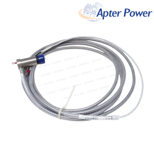
- Match the transmitter to the installed 3300 NSv sensing chain using the confirmed loop documentation.
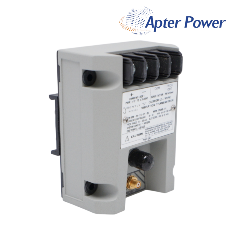
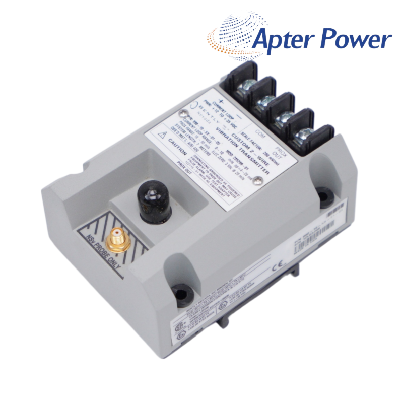
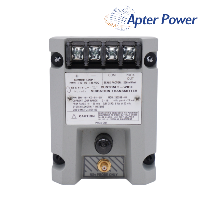
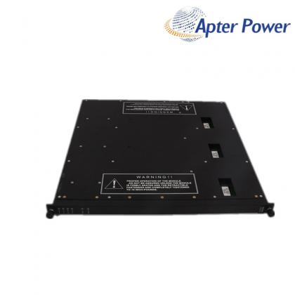
A 0-10 mil peak-to-peak two-wire vibration transmitter with DIN mounting, 4-20 mA output and the multiple-approval option.
Item NO.:
990-10-XX-01-05Order(MOQ):
1Goods Stock:
13Payment:
T/TLead Time:
In stockWeight:
0.5kgDimension:
10x7.3x5.5cmDescription:
990 Vibration TransmitterPrice:
AskA 0-10 mil peak-to-peak two-wire vibration transmitter with DIN mounting, 4-20 mA output and the multiple-approval option.
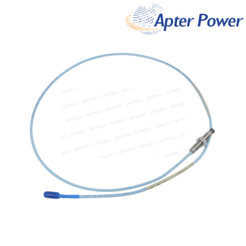
The 990 transmitter accepts a matched 3300 NSv probe and extension cable and sends proportional vibration as a 4-20 mA loop signal. A buffered Prox Out point supports field diagnosis without disturbing the control-system channel. The 10 mil range and two-wire output make 990-10-XX-01-05 suitable for a direct radial-vibration loop into a control system.
Code 10 sets a 0-10 mil peak-to-peak full-scale range, code 01 selects 35 mm DIN-rail clips and code 05 identifies the multiple-approval version. Together, those confirmed options define 990-10-XX-01-05 as a DIN-mounted 10 mil transmitter with the published 990 electrical and environmental limits.
During commissioning, scale 990-10-XX-01-05 for 4 mA at zero and 20 mA at 10 mil peak-to-peak, then compare Prox Out with the DCS value under a known machine condition. That comparison separates sensing-chain behavior from loop wiring or channel scaling.
Use a +12 to +35 Vdc supply at the transmitter terminal and include field cable plus the receiving-channel input resistance in the loop calculation before commissioning.
After confirming the exact unit, configure 4 mA as zero vibration and 20 mA as 10 mil peak-to-peak, then prove the loop with a controlled test signal.
It is the Not OK/Signal Defeat response. Check the probe gap, coaxial path, supply voltage and connector condition before replacing the transmitter.
The supplied unit should carry the applicable CSA Division 2, ATEX and ABS markings stated for option 05. Matching the complete nameplate to the project classification helps avoid an unsuitable installation.
It exposes the buffered proximity signal at the transmitter. If Prox Out is healthy but the DCS value is not, focus on loop wiring, scaling and channel configuration.
The enclosure may experience condensing humidity, but the transmitter must not be submerged and the coaxial connectors need protection. Moisture at the connector can disturb both Prox Out and the 4-20 mA signal.
Products supplied by ApterPLC are covered for 12 months under the applicable sales terms. Keep the complete unit nameplate and transaction record so the exact product can be identified during technical support.
The attached selection contains the official description, performance data, environmental limits, ordering codes and product drawings relevant to 990-10-XX-01-05. Unrelated catalog pages have been removed.
|
3300/53 |
4454-156 |
1701/15 |
|
3300/21 |
16137-174 |
136294-01 |
|
990-04-XX-01-CN |
16137-177 |
330180-52-05 |
|
330354-040-24-05 |
330980-70-05 |
330104-00-06-10-02-00 |
|
330930-045-00-00 |
330180-92-05 |
330104-00-06-10-11-00 |
|
330130-070-00-CN |
177230-01-01-CN |
330104-00-07-05-02-00 |
|
3500/93 135799-02 |
330930-060-00-05 |
330103-11-19-10-02-00 |
|
3500/93 135785-02 |
3500/62 133811-03 |
330104-00-07-90-02-00 |
|
330103-05-15-05-02-00 |
3500/70M 140734-09 |
330104-00-08-05-02-00 |
|
330104-00-15-10-02-00 |
330905-08-13-10-02-05 |
330104-05-13-10-02-00 |
|
330106-05-30-50-02-00 |
330104-01-08-10-01-05 |
330104-05-15-05-02-00 |
|
330907-05-30-05-02-05 |
330101-00-20-05-02-05 |
330104-06-12-10-02-00 |
|
330106-05-30-20-02-CN |
330104-06-14-50-02-00 |
330104-10-18-10-01-00 |
|
330103-00-05-20-02-CN |
330103-00-04-10-12-00 |
330104-00-06-10-02-CN |
|
330851-02-000-030-10-00-05 |
330105-02-12-90-02-05 |
330104-00-07-10-02-CN |
Related Tags :

SALES SUPPORT
32D floor,Guomao building,Hubin South Road,Siming District,Xiamen,Fujian,China.


Apter Power sells new and surplus products and develops channels for purchasing such products. This website has not been approved or recognized by any of the listed manufacturers or trademarks.
Apter Power is not an authorized distributor, dealer, or representative of the products displayed on this website. All product names, trademarks, brands, and logos used on this website are the property of their respective owners. The description, explanation, or sale of products with these names, trademarks, brands, and logos is for identification purposes only and is not intended to indicate any association with or authorization from any rights holder.