

Selection
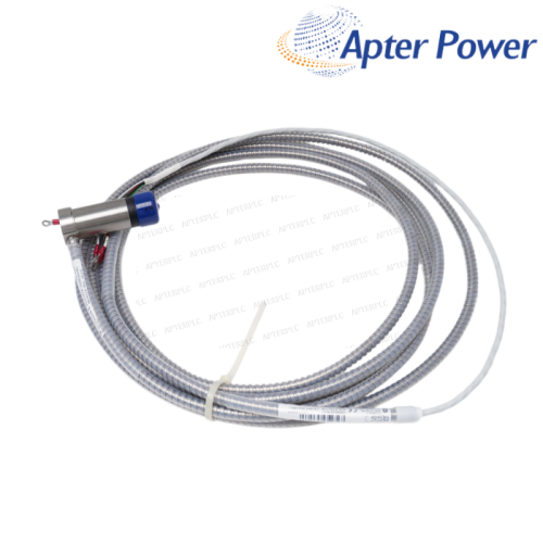
- Match the 7 m NSv chain, 5 mil range and bulkhead hardware.
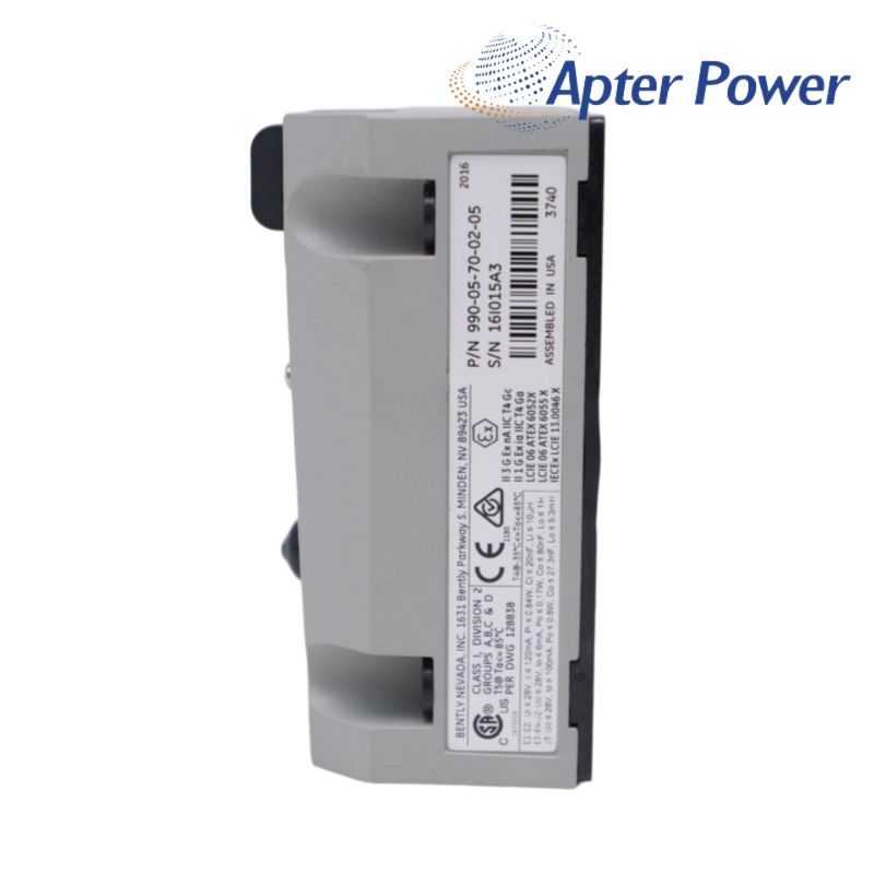
- Confirm code 05 markings against the approved area and marine documentation.
Item NO.:
990-05-70-02-05Order(MOQ):
1Goods Stock:
12Payment:
T/TLead Time:
In stockWeight:
0.55KGDimension:
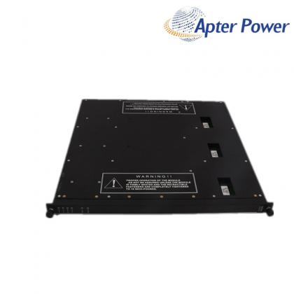
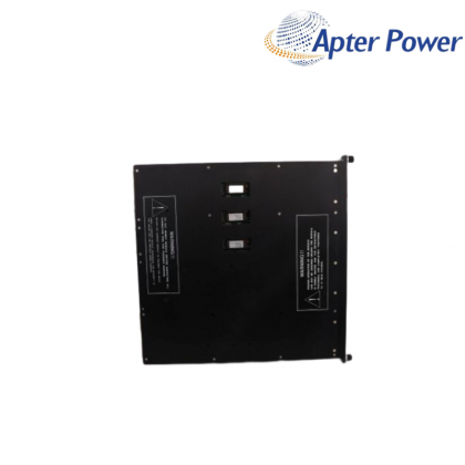
7.8x3x6.2cmDescription:
TRANSMITTERPrice:
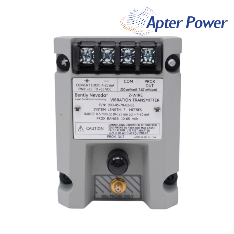
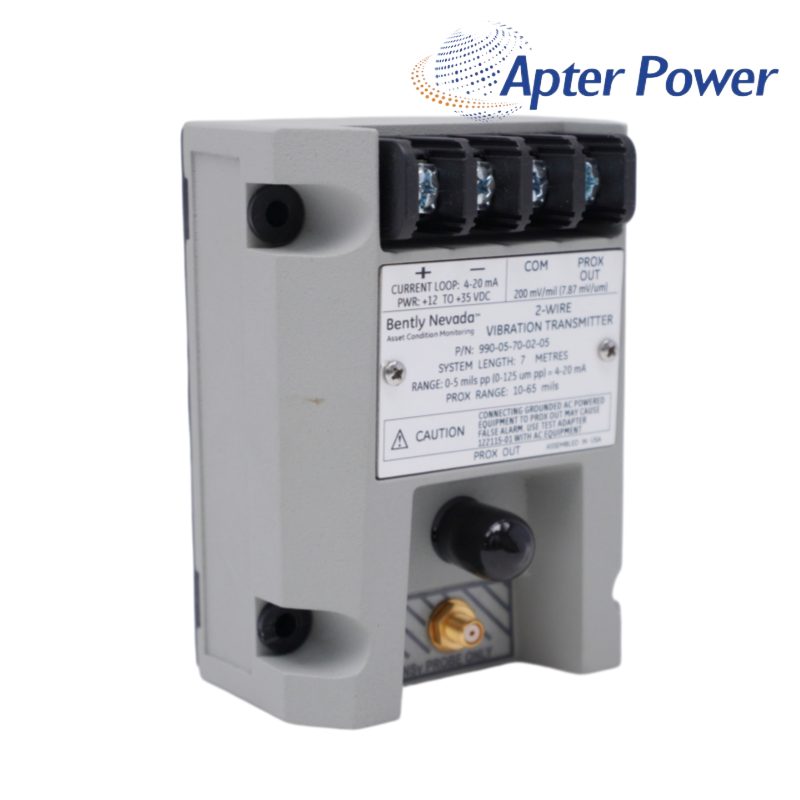
AskA 5 mil full-scale, 7.0 m bulkhead vibration transmitter with the multi-agency approval option.
This approved 990 transmitter is intended for machinery packages that need a simple 4–20 mA shaft-vibration signal and a 7.0 m NSv transducer path. The bulkhead arrangement keeps the electronics accessible at an enclosure or panel while the probe remains at the machine.
Its suffix combines a 0–5 mil peak-to-peak range, 7.0 m system length, bulkhead mounting screws and the multi-approval option. Those approvals must still be matched to the markings on the supplied unit and to the site’s barriers, wiring method and area-classification drawing.
For a useful handover, commission both outputs: prove the control-system loop across the full scale and capture the Prox Out bias and waveform at a known machine state. The two records make later fault-finding much faster than a loop value alone.
The supplied-unit approval markings, area classification, barrier schedule, wiring method and grounding arrangement should all agree with the approved installation design.
The probe lead and extension-cable lengths should add up to 7.0 m so the installed chain matches the transmitter calibration.
The installation should leave safe access to the terminals and diagnostic point while providing suitable cable-entry space, grounding and wire bend clearance.
The normal mapping is 4 mA at zero vibration and 20 mA at 5 mil peak-to-peak; verify the site configuration and units during the loop test.
It does not prove probe gap, target condition, waveform quality or correct system length. Check Prox Out and the complete NSv chain as well.
Inspect supply headroom, bulkhead terminals, shield and ground treatment, probe gap, connectors and cable damage before changing the transmitter or DCS scaling.
Products supplied by ApterPLC are covered for 12 months under the applicable sales terms. The complete nameplate and transaction record help our team identify the exact unit when support is needed.
This Bently Nevada document covers operation, electrical specifications, wiring and ordering information for 990-05-70-02-05. It provides a practical reference for model selection, installation planning and maintenance.
|
330104-06-12-10-02-00 |
330130-035-00-00 |
330130-040-02-00 |
|
330104-06-14-50-02-00 |
330130-035-00-CN |
330130-045-00-00 |
|
330104-10-18-10-01-00 |
330130-030-01-CN |
330130-045-00-05 |
|
330104-10-20-05-02-00 |
330106-00-04-10-02-00 |
330130-040-00-00 |
|
330104-10-20-10-02-05 |
330106-05-30-05-02-00 |
330130-040-00-05 |
|
330104-12-20-10-01-00 |
330105-02-12-50-02-00 |
330130-040-01-05 |
|
330104-13-20-10-02-00 |
330106-05-30-10-02-00 |
330130-045-01-00 |
|
330104-15-23-10-02-00 |
330106-05-30-10-02-05 |
330130-045-02-05 |
|
330104-19-25-10-11-05 |
330106-05-30-15-02-00 |
330130-045-03-05 |
|
330105-02-12-05-02-00 |
330106-05-30-50-02-00 |
330130-035-01-CN |
|
330105-02-12-05-02-05 |
330130-00-05-05-02-00 |
330130-045-00-CN |
|
330105-02-12-10-02-00 |
330106-05-30-05-02-CN |
330130-045-01-CN |
|
330105-02-12-15-12-05 |
330106-05-30-10-02-CN |
330130-040-00-CN |
|
330105-02-12-15-12-CN |
330106-05-30-15-02-CN |
330130-040-02-CN |
|
330105-02-12-05-02-CN |
330106-05-30-20-02-CN |
330130-040-10-CN |
Related Tags :

SALES SUPPORT
32D floor,Guomao building,Hubin South Road,Siming District,Xiamen,Fujian,China.


Apter Power sells new and surplus products and develops channels for purchasing such products. This website has not been approved or recognized by any of the listed manufacturers or trademarks.
Apter Power is not an authorized distributor, dealer, or representative of the products displayed on this website. All product names, trademarks, brands, and logos used on this website are the property of their respective owners. The description, explanation, or sale of products with these names, trademarks, brands, and logos is for identification purposes only and is not intended to indicate any association with or authorization from any rights holder.