

Selection
- Confirm the M14 × 1.5 mount, 120 mm reach and required 11 mm measurement range.
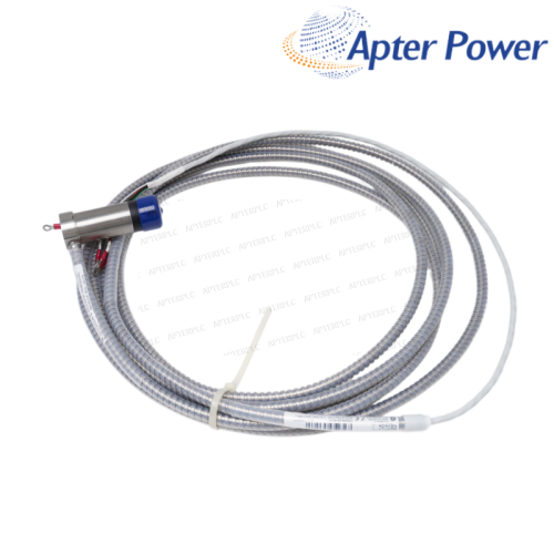
- Check whether the installed sensor is a 5 m or 9 m 330780 configuration before choosing the extension cable.
Item NO.:
330703-000-120-10-02-00Order(MOQ):
1Goods Stock:
13Payment:
T/TLead Time:
In stockWeight:
2.0KGDimension:
21.5x23x3.5cmDescription:
PROXIMITY PROBESPrice:
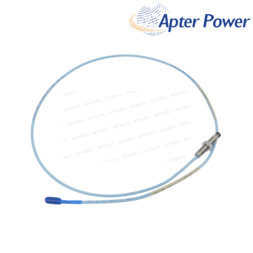
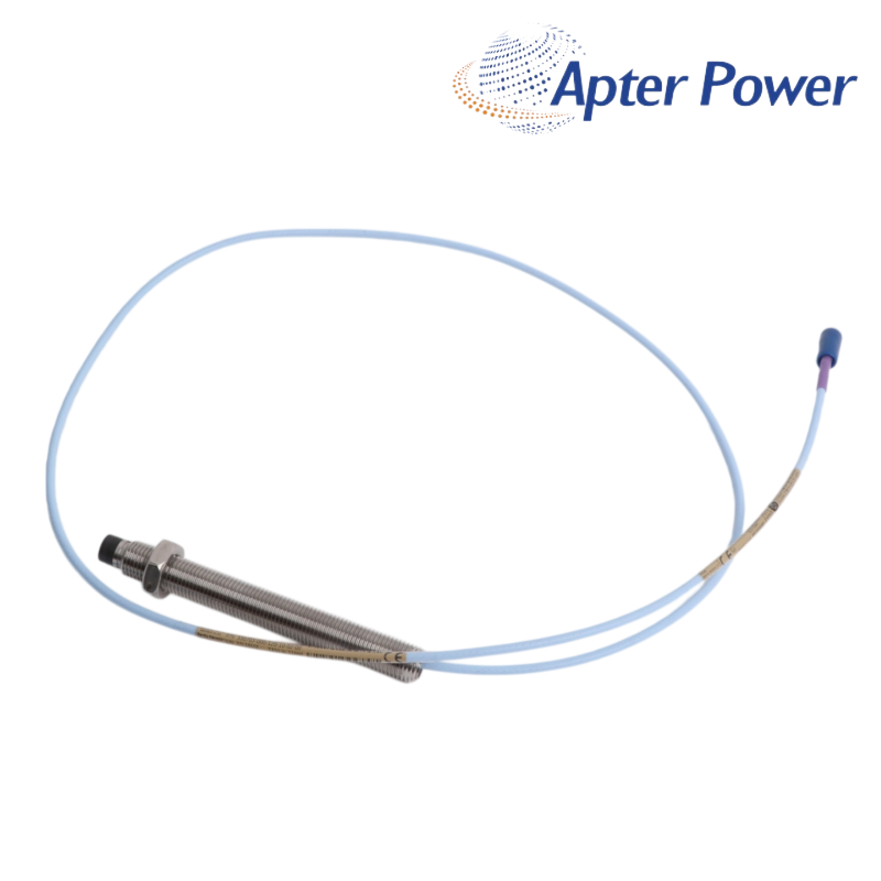
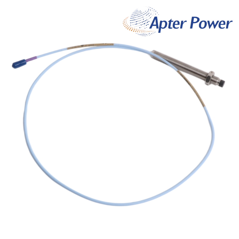
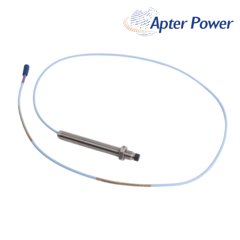
AskAn M14 × 1.5 unarmored 11 mm probe with a 120 mm case and 1.0 m standard lead for wider-range shaft position measurements.
When a standard 8 mm system does not offer enough measurement travel, the 4 mm linear range of the 3300 XL 11 mm system makes 330703-000-120-10-02-00 a practical choice for axial position, ramp differential expansion and other wider-range shaft measurements.
A 120 mm case gives 330703-000-120-10-02-00 the reach needed for deeper M14 × 1.5 bearing-housing or bracket locations. The 1.0 m lead and miniature ClickLoc connection keep the field connection compact without adding armor to the cable route.
Specified performance comes from the complete 11 mm measurement chain rather than the probe alone. Pair 330703-000-120-10-02-00 with the appropriate 330730 extension cable and 330780 Proximitor Sensor so the probe and cable total matches the selected 5 m or 9 m system.
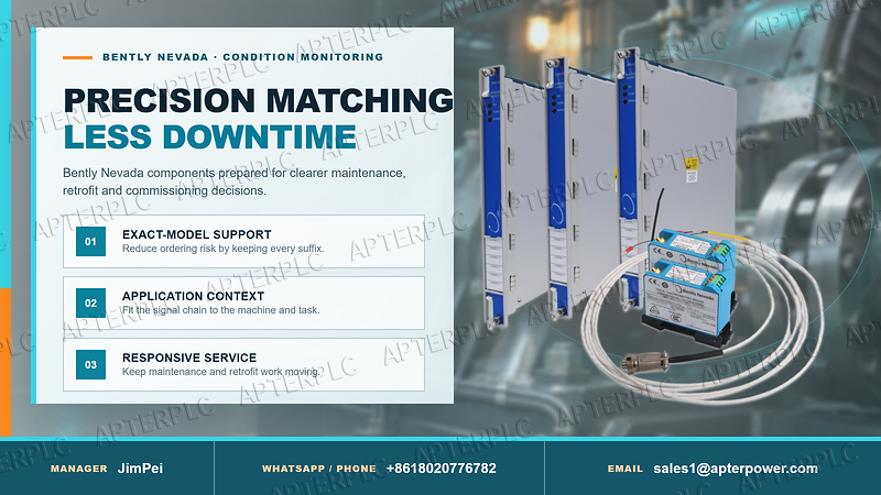
Use it at an M14 × 1.5 bearing-housing or bracket point that needs the 11 mm system’s 4 mm linear range for axial position, ramp differential expansion, rod position or another engineered wider-range measurement. Confirm the actual target and channel task before selection.
Compare the original drawing, insertion depth, locknut position and available thread engagement. Dry-fit the mechanical reach with the machine safe, then confirm that the tip can be electrically gapped without contacting the target or exhausting adjustment.
Use a 330730 11 mm extension cable and a 330780 Proximitor Sensor. Add the 1.0 m probe lead to the extension-cable length so the total equals the selected 5 m or 9 m sensor configuration.
Record the full part number, extension-cable and sensor models, final gap voltage, shaft state, channel scale, cable route and machine operating condition. These values create the baseline needed to judge later drift.
Recheck insertion depth, target condition, ClickLoc seating, total system length and channel scale before changing alarms. If the bias is unstable, then test cable continuity and sensor supply.
Match the M14 × 1.5 thread, 0 mm unthreaded length, 120 mm case, 1.0 m lead, connector code 02 and approval code 00 to the installed record—not only the 330703 family name.
Supplied products are covered for 12 months under ApterPLC sales terms. Keep the complete nameplate, original packaging and transaction record so the exact unit and revision can be identified during support.
Support: sales1@apterpower.com · +8618020776782
Use this document to review the 3300 XL 11 mm probe ordering code, dimensional drawings, system matching requirements and the specifications that apply to this 120 mm metric configuration.
Download the 330703-000-120-10-02-00 filtered official datasheet|
3300/53 |
4454-156 |
1701/15 |
|
3300/21 |
16137-174 |
136294-01 |
|
990-04-XX-01-CN |
16137-177 |
330180-52-05 |
|
330354-040-24-05 |
330980-70-05 |
330104-00-06-10-02-00 |
|
330930-045-00-00 |
330180-92-05 |
330104-00-06-10-11-00 |
|
330130-070-00-CN |
177230-01-01-CN |
330104-00-07-05-02-00 |
|
3500/93 135799-02 |
330930-060-00-05 |
330103-11-19-10-02-00 |
|
3500/93 135785-02 |
3500/62 133811-03 |
330104-00-07-90-02-00 |
|
330103-05-15-05-02-00 |
3500/70M 140734-09 |
330104-00-08-05-02-00 |
|
330104-00-15-10-02-00 |
330905-08-13-10-02-05 |
330104-05-13-10-02-00 |
|
330106-05-30-50-02-00 |
330104-01-08-10-01-05 |
330104-05-15-05-02-00 |
|
330907-05-30-05-02-05 |
330101-00-20-05-02-05 |
330104-06-12-10-02-00 |
|
330106-05-30-20-02-CN |
330104-06-14-50-02-00 |
330104-10-18-10-01-00 |
|
330103-00-05-20-02-CN |
330103-00-04-10-12-00 |
330104-00-06-10-02-CN |
|
330851-02-000-030-10-00-05 |
330105-02-12-90-02-05 |
330104-00-07-10-02-CN |
Related Tags :

SALES SUPPORT
32D floor,Guomao building,Hubin South Road,Siming District,Xiamen,Fujian,China.


Apter Power sells new and surplus products and develops channels for purchasing such products. This website has not been approved or recognized by any of the listed manufacturers or trademarks.
Apter Power is not an authorized distributor, dealer, or representative of the products displayed on this website. All product names, trademarks, brands, and logos used on this website are the property of their respective owners. The description, explanation, or sale of products with these names, trademarks, brands, and logos is for identification purposes only and is not intended to indicate any association with or authorization from any rights holder.