

Confirm the VM600 rack type, rear position and backplane compatibility.
Item NO.:
200-570-000-211Order(MOQ):
1Goods Stock:
12Payment:
T/TLead Time:
In stockWeight:
0.3KGDimension:
10.5x7.6x10.2cmDescription:
RELAY CARDPrice:
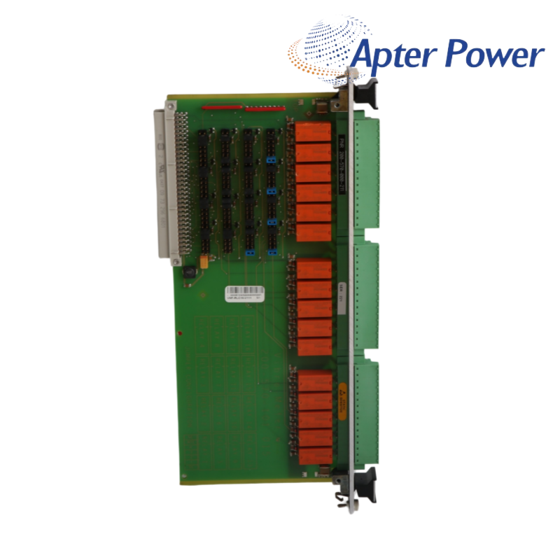
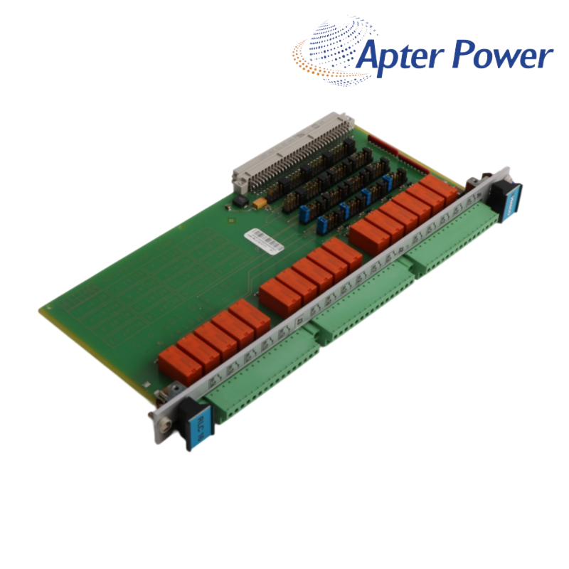
AskA VM600 rear-rack relay card providing 16 change-over relays for additional alarm and trip outputs.
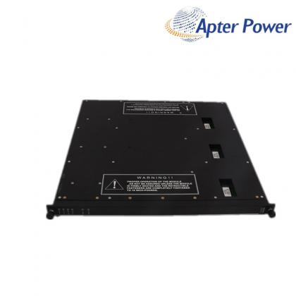
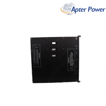
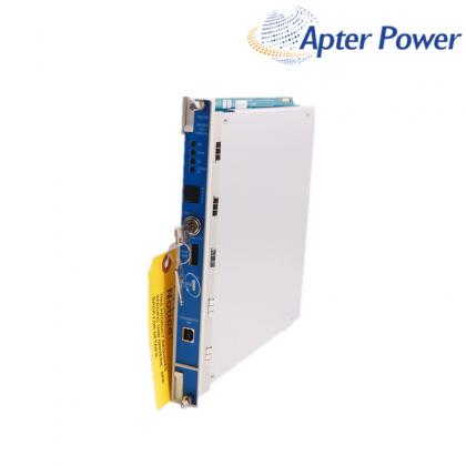
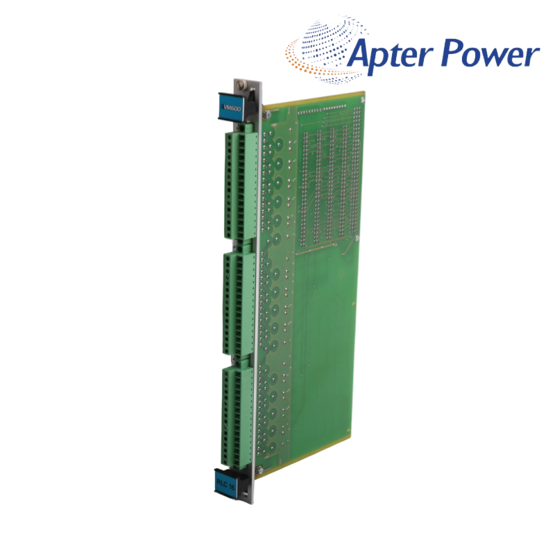
16 change-over relays · rear-rack mounting · screw terminals · jumper-selectable relay state200-570-000-211 is an RLC16 relay card for the Vibro-Meter VM600 machinery protection system. The RLC16 provides 16 independent change-over relays when the integral relay capacity of the paired I/O arrangement is insufficient.
Installed at the rear of the VM600 rack, 200-570-000-211 connects to the backplane. Three screw-terminal connectors expose one COM, one NC and one NO contact for each relay, while onboard jumpers select normally energized or normally de-energized behavior.
For a reliable replacement, match 200-570-000-211 to the nameplate, rack type, jumper map and terminal schedule that define the installed hardware execution.
Exact RLC16 ordering reference
VM600 relay expansion card
16 change-over relays
Rear screw-terminal connectors
| VERIFIED TECHNICAL DATA | |
|---|---|
| Manufacturer | Vibro-Meter / Meggitt |
| System | VM600 machinery protection |
| Module type | RLC16 relay card |
| Relay quantity | 16 |
| Contact arrangement | 1 COM + 1 NC + 1 NO per relay |
| Nominal rated voltage | 250 VAC |
| Nominal rated current | 5 A AC |
| Maximum breaking capacity | 1250 VA |
| Operate / release / bounce | 8 / 8 / 6 ms typical |
| Relay state | Normally energized or de-energized |
| External connections | Screw terminals J1, J2 and J3 |
| Mounting | Rear VM600 rack / backplane |
| Exact hardware | Verify 200-570-000-211 nameplate |
| SUPPLY & LOGISTICS | |
| Place of shipment | Xiamen, China |
| Delivery Time | 1-3 days |
| Quantity | 100% New Original |
| Minimum Order Quantity | 1pc |
Confirm the VM600 rack type, rear position and backplane compatibility.
Record every NE or NDE jumper before removing the existing card.
Photograph J1, J2 and J3 wiring and identify each connected load.
Verify switching voltage, current and suppression for every relay circuit.
Match the rack layout, backplane position and the controlling VM600 hardware. An available physical slot alone does not confirm compatibility.
Record the NE or NDE jumper state for all 16 relays and reproduce the terminal map before returning the card to service.
Each relay uses COM, NC and NO contacts distributed across J1, J2 and J3. Use the installed drawing and label rather than wire color alone.
Confirm voltage, current, breaking capacity, contact protection and the slimline-rack derating note where applicable.
A different jumper state, software relay assignment or terminal landing can invert the expected logic even when the card powers normally.
Provide front and rear labels, rack model, hardware version, jumper photos, terminal schedule and the installed VM600 card pairing.
Complete labels and order fields are checked before quotation.
Probe, cable, rack and monitoring roles are reviewed together.
Commercial terms, documents and delivery are confirmed in writing.
Coverage begins on the shipment date unless the confirmed quotation states otherwise. Scope, exclusions and available remedy follow the written quotation and sales agreement.
Provide the complete 200-570-000-211 label and order reference.
Add mounting, connector, rack and signal-chain photos.
Describe the symptom, operating state and first occurrence.
Include the applicable sales document and shipment date.
Share the complete product label and tell us whether you need a datasheet, user manual, wiring diagram or other technical document. Installed-system details can help us identify the most relevant available manufacturer material.
Our team will review the available documents and help match the closest useful file for 200-570-000-211.
WhatsApp: +8618020776782Email: sales1@apterpower.comRelated Tags :

SALES SUPPORT
32D floor,Guomao building,Hubin South Road,Siming District,Xiamen,Fujian,China.


Apter Power sells new and surplus products and develops channels for purchasing such products. This website has not been approved or recognized by any of the listed manufacturers or trademarks.
Apter Power is not an authorized distributor, dealer, or representative of the products displayed on this website. All product names, trademarks, brands, and logos used on this website are the property of their respective owners. The description, explanation, or sale of products with these names, trademarks, brands, and logos is for identification purposes only and is not intended to indicate any association with or authorization from any rights holder.