

Selection
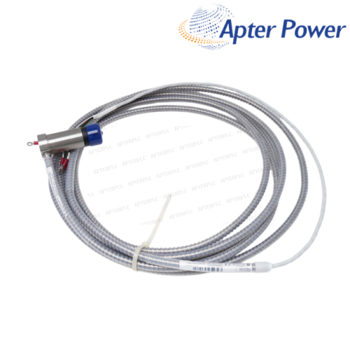
- Confirm the required ±25 mil range and the 5 m NSv chain.
- Check DIN-rail space, loop supply and code 05 site approvals before ordering.
Item NO.:
991-25-50-01-05Order(MOQ):
1Goods Stock:
12Payment:
T/TLead Time:
In stockWeight:
0.55KGDimension:
7.8x3x6.2cmDescription:
TRANSMITTERPrice:
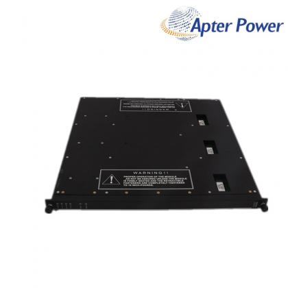
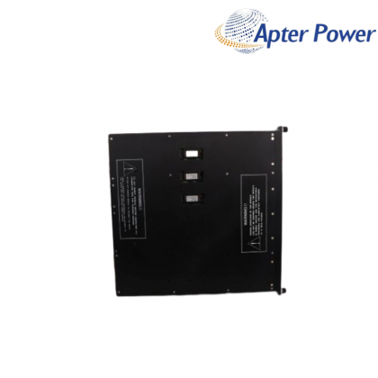
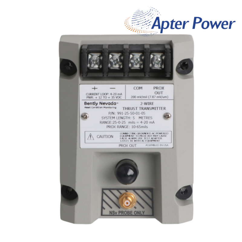
AskA ±25 mil, 5.0 m DIN-rail axial-position transmitter with a two-wire 4–20 mA loop and multi-agency approvals.
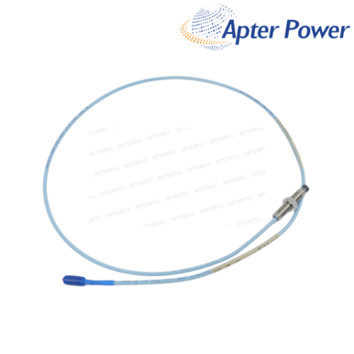
The 991 transmitter converts axial shaft position from a 3300 NSv probe into a proportional 4–20 mA signal for a machinery control system. It is intended for thrust or position monitoring where the operator needs a simple control-loop value alongside direct access to the proximity signal.
This configuration provides a ±25 mil measurement range, a matched 5.0 m probe-and-cable system, DIN-rail mounting and the multi-approval option. Zero and span adjustments allow the installed mechanical reference to be aligned with the control-system scale during commissioning.
Good thrust data depends on more than wiring the loop. The shaft reference position, probe gap, direction of increasing current and trip philosophy must all be agreed before the machine returns to service, then recorded so later position changes can be interpreted correctly.
Use the plant’s defined axial reference—often a known rotor position or mechanical setup—and record that condition before setting the loop midpoint.
The configured midpoint represents zero reference, with current moving toward either end of the loop as the shaft moves through the positive or negative position range.
A reversed mechanical or electrical sense can make a dangerous movement look safe. Confirm the direction of increasing current against the control-system display and trip logic.
Check loop supply, probe gap, NSv cable continuity, transmitter status and the documented startup inhibit behavior before changing zero or span.
A normal loop value does not by itself show bias, noise, runout or waveform quality. Prox Out provides the direct signal needed to investigate those conditions.
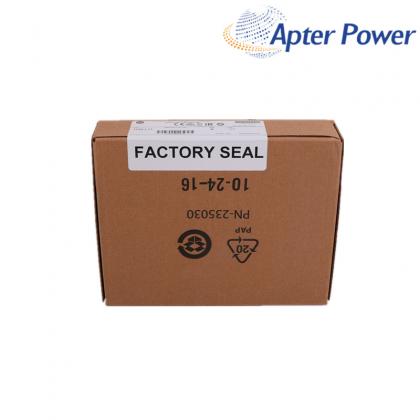
Keep the mechanical reference, zero and span settings, probe gap, loop current, channel scale, alarm direction and a photo of the complete model and approval markings.
Products supplied by ApterPLC are covered for 12 months under the applicable sales terms. The complete nameplate and transaction record help our team identify the exact unit when support is needed.
This Bently Nevada document covers operation, electrical specifications, calibration and ordering information for 991-25-50-01-05. It provides a practical reference for model selection, installation planning and maintenance.
|
330104-06-12-10-02-00 |
330130-035-00-00 |
330130-040-02-00 |
|
330104-06-14-50-02-00 |
330130-035-00-CN |
330130-045-00-00 |
|
330104-10-18-10-01-00 |
330130-030-01-CN |
330130-045-00-05 |
|
330104-10-20-05-02-00 |
330106-00-04-10-02-00 |
330130-040-00-00 |
|
330104-10-20-10-02-05 |
330106-05-30-05-02-00 |
330130-040-00-05 |
|
330104-12-20-10-01-00 |
330105-02-12-50-02-00 |
330130-040-01-05 |
|
330104-13-20-10-02-00 |
330106-05-30-10-02-00 |
330130-045-01-00 |
|
330104-15-23-10-02-00 |
330106-05-30-10-02-05 |
330130-045-02-05 |
|
330104-19-25-10-11-05 |
330106-05-30-15-02-00 |
330130-045-03-05 |
|
330105-02-12-05-02-00 |
330106-05-30-50-02-00 |
330130-035-01-CN |
|
330105-02-12-05-02-05 |
330130-00-05-05-02-00 |
330130-045-00-CN |
|
330105-02-12-10-02-00 |
330106-05-30-05-02-CN |
330130-045-01-CN |
|
330105-02-12-15-12-05 |
330106-05-30-10-02-CN |
330130-040-00-CN |
|
330105-02-12-15-12-CN |
330106-05-30-15-02-CN |
330130-040-02-CN |
|
330105-02-12-05-02-CN |
330106-05-30-20-02-CN |
330130-040-10-CN |
Related Tags :

SALES SUPPORT
32D floor,Guomao building,Hubin South Road,Siming District,Xiamen,Fujian,China.


Apter Power sells new and surplus products and develops channels for purchasing such products. This website has not been approved or recognized by any of the listed manufacturers or trademarks.
Apter Power is not an authorized distributor, dealer, or representative of the products displayed on this website. All product names, trademarks, brands, and logos used on this website are the property of their respective owners. The description, explanation, or sale of products with these names, trademarks, brands, and logos is for identification purposes only and is not intended to indicate any association with or authorization from any rights holder.