

Selection
- Confirm the ±0.6 mm thrust range, DIN mounting and no-approval option against the control-system loop sheet.
- Review loop supply, available resistance and the matched 3300 NSv input path before commissioning.
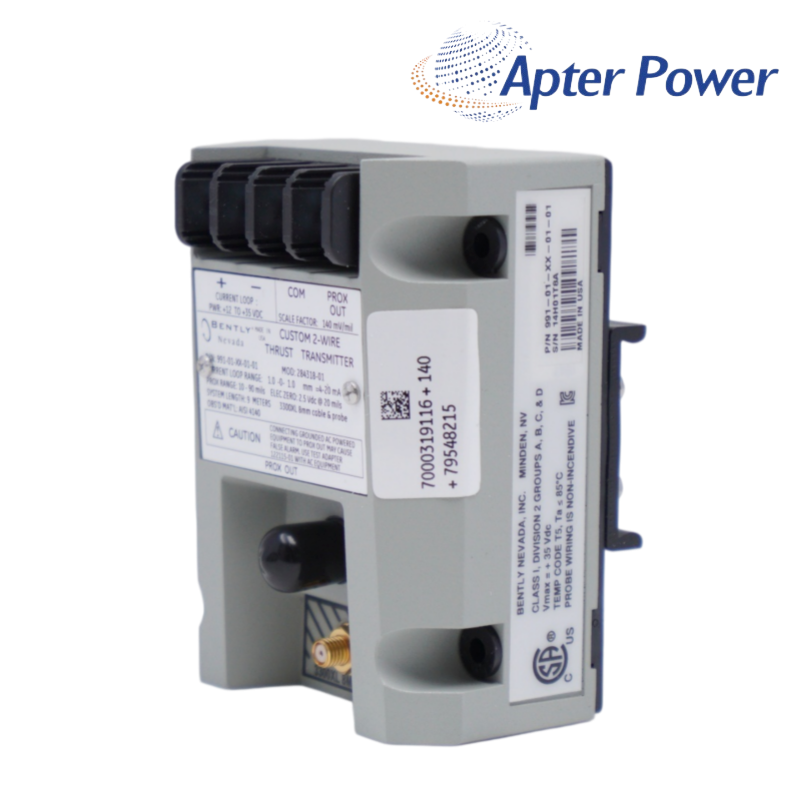
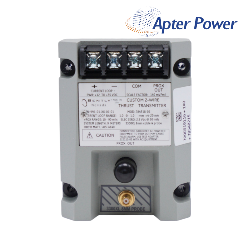
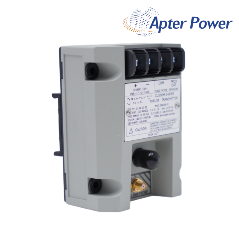
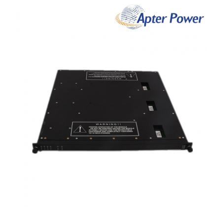
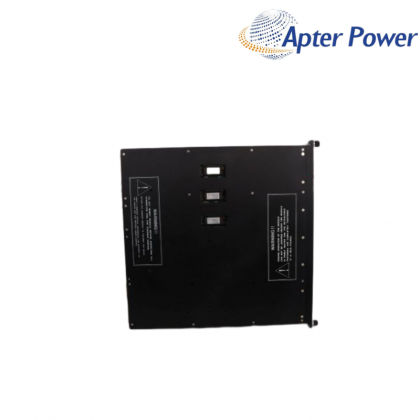
A ±0.6 mm two-wire thrust transmitter with DIN-rail mounting, 4-20 mA output and a buffered Prox Out diagnostic signal.
Item NO.:
991-06-XX-01-00Order(MOQ):
1Goods Stock:
12Payment:
T/TLead Time:
In stockWeight:
0.5kgDimension:
10x7.3x5.6cmDescription:
991 Thrust TransmitterPrice:
AskA ±0.6 mm two-wire thrust transmitter with DIN-rail mounting, 4-20 mA output and a buffered Prox Out diagnostic signal.
The 991 family converts axial position from a matched 3300 NSv proximity chain into a 4-20 mA signal for a PLC, DCS or other plant control system. Its zero and span controls support field setup around the machine thrust reference. In this loop, 991-06-XX-01-00 converts axial position into a two-wire signal that the control system can trend directly.
For this listed string, code 06 defines a 0.6-0-0.6 mm range, code 01 selects 35 mm DIN-rail clips and code 00 specifies no agency approval option. Together, those confirmed options place 991-06-XX-01-00 in a DIN-mounted, no-approval thrust loop with the published 991 electrical performance.
Commission 991-06-XX-01-00 with the rotor at a known axial reference, then compare the buffered Prox Out signal with loop current and the DCS direction. That baseline makes later separation of probe-chain, wiring and scaling faults much faster.
At 35 Vdc the complete loop resistance can be up to 1,000 Ω, including field cable. Calculate the actual supply headroom and input resistance before commissioning so the transmitter can reach its full output range.
Place the rotor at the documented mechanical reference, confirm probe gap and direction, then set zero and span while comparing Prox Out with the 4-20 mA loop.
Verify probe orientation, terminal polarity, loop scaling and the configured engineering-unit direction before changing alarm logic.
It is the transmitter Not OK/Signal Defeat response. Check supply voltage, probe gap, cable continuity and connector condition before replacing the transmitter.
Compare the buffered Prox Out signal with the loop current. A credible Prox Out value with an incorrect DCS reading directs attention toward loop wiring, input scaling or channel configuration rather than the probe signal.
The transmitter normally limits output near 23 mA. A current at that ceiling indicates a loop or over-range condition to investigate; it is not an additional calibrated measurement point.
Products supplied by ApterPLC are covered for 12 months under the applicable sales terms. Keep the complete unit nameplate and transaction record so the exact product can be identified during technical support.
The attached selection contains the official description, performance data, environmental limits, ordering codes and product drawings relevant to 991-06-XX-01-00. Unrelated catalog pages have been removed.
|
330104-06-12-10-02-00 |
330130-035-00-00 |
330130-040-02-00 |
|
330104-06-14-50-02-00 |
330130-035-00-CN |
330130-045-00-00 |
|
330104-10-18-10-01-00 |
330130-030-01-CN |
330130-045-00-05 |
|
330104-10-20-05-02-00 |
330106-00-04-10-02-00 |
330130-040-00-00 |
|
330104-10-20-10-02-05 |
330106-05-30-05-02-00 |
330130-040-00-05 |
|
330104-12-20-10-01-00 |
330105-02-12-50-02-00 |
330130-040-01-05 |
|
330104-13-20-10-02-00 |
330106-05-30-10-02-00 |
330130-045-01-00 |
|
330104-15-23-10-02-00 |
330106-05-30-10-02-05 |
330130-045-02-05 |
|
330104-19-25-10-11-05 |
330106-05-30-15-02-00 |
330130-045-03-05 |
|
330105-02-12-05-02-00 |
330106-05-30-50-02-00 |
330130-035-01-CN |
|
330105-02-12-05-02-05 |
330130-00-05-05-02-00 |
330130-045-00-CN |
|
330105-02-12-10-02-00 |
330106-05-30-05-02-CN |
330130-045-01-CN |
|
330105-02-12-15-12-05 |
330106-05-30-10-02-CN |
330130-040-00-CN |
|
330105-02-12-15-12-CN |
330106-05-30-15-02-CN |
330130-040-02-CN |
|
330105-02-12-05-02-CN |
330106-05-30-20-02-CN |
330130-040-10-CN |
Related Tags :

SALES SUPPORT
32D floor,Guomao building,Hubin South Road,Siming District,Xiamen,Fujian,China.


Apter Power sells new and surplus products and develops channels for purchasing such products. This website has not been approved or recognized by any of the listed manufacturers or trademarks.
Apter Power is not an authorized distributor, dealer, or representative of the products displayed on this website. All product names, trademarks, brands, and logos used on this website are the property of their respective owners. The description, explanation, or sale of products with these names, trademarks, brands, and logos is for identification purposes only and is not intended to indicate any association with or authorization from any rights holder.