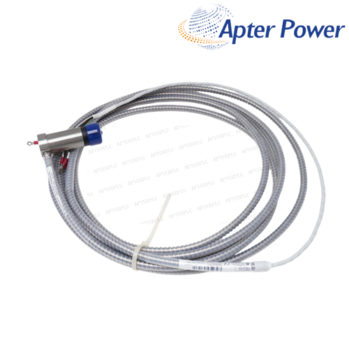


Use the delivered label or historical project document to establish the exact measuring range before replacement.
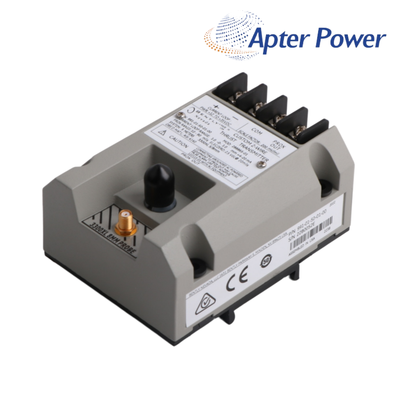
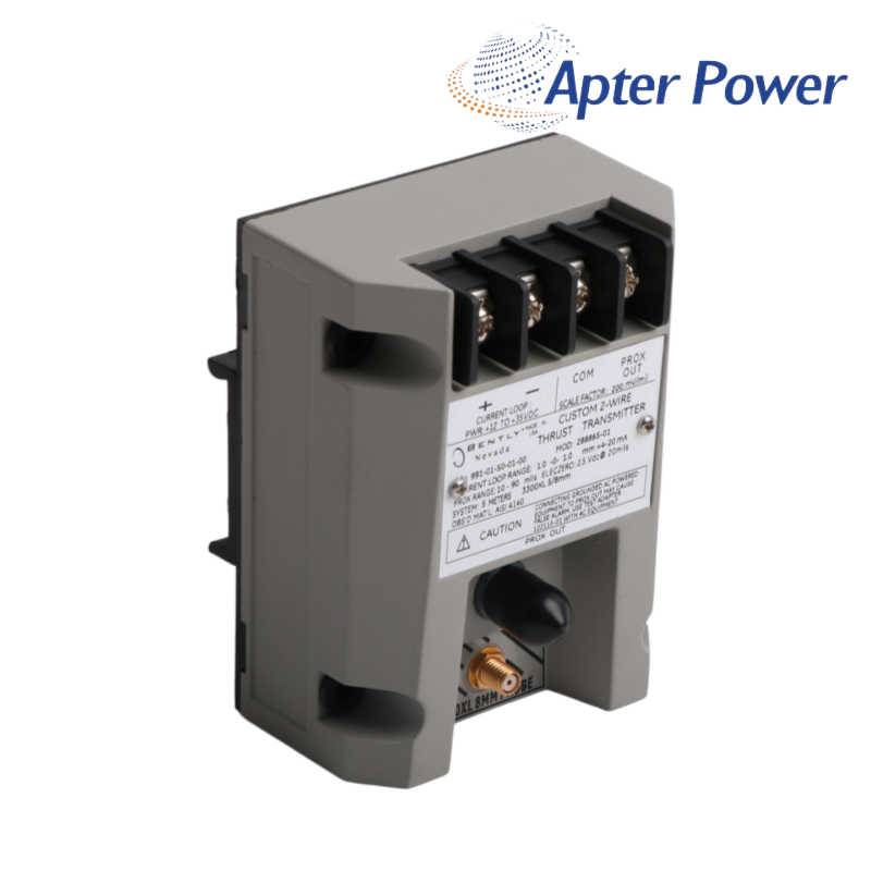
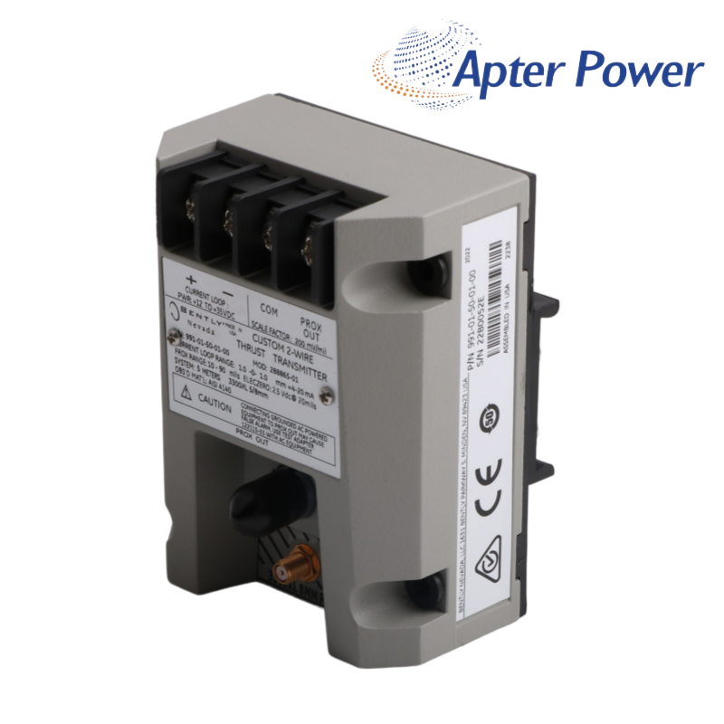
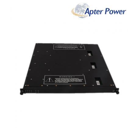
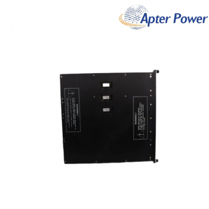
A two-wire 4-20 mA thrust / axial-position transmitter identified by the installed label and MOD 288865-01. 991 family · 5.0 m system field · DIN clips · no approval · MOD 288865-01 label review.
Item NO.:
991-01-50-01-00Order(MOQ):
1Goods Stock:
10Payment:
T/TLead Time:
In stockWeight:
1.87KGDimension:
7.5x12.6x 3.6cmDescription:
CONTROLLERPrice:
AskA two-wire 4-20 mA thrust / axial-position transmitter identified by the installed label and MOD 288865-01.
991 family · 5.0 m system field · DIN clips · no approval · MOD 288865-01 label reviewThe 991 transmitter family brings proximity-based thrust or axial-position measurement into a two-wire 4-20 mA loop. On 991-01-50-01-00 288865-01, the 50 field identifies a 5.0 m transducer-system length and the 01 field identifies DIN-rail clips.
The currently published manufacturer order table no longer lists the 01 range option or MOD 288865-01. For that reason, the delivered nameplate remains essential when matching 991-01-50-01-00 288865-01 to its mechanical zero position, range and connected NSv chain.
A responsible replacement offer for 991-01-50-01-00 288865-01 should preserve the full historical identity rather than substituting a current 991 range by appearance. ApterPLC can compare the label, loop scaling and installed transducer details before quotation.
Thrust transmitter family
Historical range field; label confirmation needed
5.0 m system length
35 mm DIN-rail clips
Approval not required
MOD identifier; current public table does not decode it
| MODEL-RELEVANT TECHNICAL DATA | |
|---|---|
| Manufacturer | Bently Nevada |
| Product family | 991 thrust transmitter |
| Component | Two-wire thrust / axial-position transmitter |
| Electrical input | One 3300 XL NSv probe and extension cable |
| Signal output | 4 to 20 mAdc |
| Loop power | +12 to +35 Vdc at transmitter terminals |
| System-length field | 50 - 5.0 m |
| Mounting option | 01 - 35 mm DIN-rail clips |
| Agency option | 00 - approval not required |
| Identity boundary | Range option 01 and MOD 288865-01 are not decoded in the current public order table |
| SUPPLY & LOGISTICS | |
| Place of shipment | Xiamen, China |
| Delivery Time | 1-3 days |
| Quantity | 100% New Original |
| Minimum Order Quantity | 1pc |
Use the delivered label or historical project document to establish the exact measuring range before replacement.
Keep the machine thrust zero and transmitter scaling tied to the same maintenance record.
Confirm that the connected NSv probe and cable form the 5.0 m input chain expected by the transmitter.
The receiving channel needs adequate loop voltage and matching engineering units for the 4-20 mA signal.
A thrust transmitter replacement should preserve the established mechanical reference rather than creating a new zero from appearance alone.
Photos of the entire label and MOD marking give the clearest basis for matching this older execution.
The highest risk is assuming the historical 01 range field equals one of the current 991 catalog ranges. The current public document does not support that equivalence, so the installed label must control the decision.
The family is still documented, but the historical 01 range and MOD are not in the current public table. A label and scaling comparison is needed before treating a current option as equivalent.
Reversed loop wiring, changed mechanical zero or mismatched receiving-channel scaling can affect interpretation; the original reference records help distinguish them.
Please share the full nameplate, MOD marking, probe and cable labels, loop range and any historical calibration or project document.
No. In the current family structure it identifies the 5.0 m transducer-system length; the historical range field needs separate evidence.
The project drawing, previous quotation, receiving-channel configuration and remaining MOD markings can be compared before selecting a replacement.
Complete labels and order fields are compared before quotation.
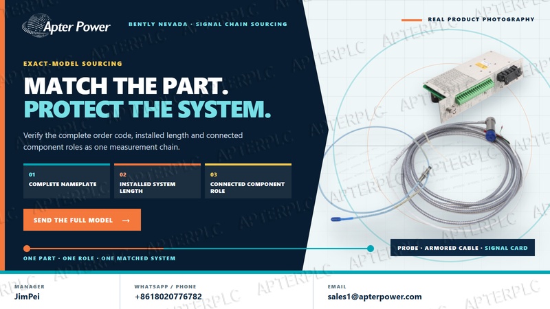
Probe, cable, sensor and transmitter roles are reviewed together.
Commercial terms, documents and delivery are confirmed in writing.
Coverage begins on the shipment date unless the confirmed quotation states otherwise. Scope, exclusions and the available remedy follow the written quotation and sales agreement.
Provide the complete 991-01-50-01-00 288865-01 label and order reference.
Add mounting, connector and signal-chain photos.
Describe the symptom, operating state and first occurrence.
ApterPLC will use the complete product label to match the most relevant available technical material for this historical or modification-controlled execution.
Our team will review the available manufacturer material and help identify the closest useful document.
WhatsApp: +8618020776782Email: sales1@apterpower.comRelated Tags :

SALES SUPPORT
32D floor,Guomao building,Hubin South Road,Siming District,Xiamen,Fujian,China.


Apter Power sells new and surplus products and develops channels for purchasing such products. This website has not been approved or recognized by any of the listed manufacturers or trademarks.
Apter Power is not an authorized distributor, dealer, or representative of the products displayed on this website. All product names, trademarks, brands, and logos used on this website are the property of their respective owners. The description, explanation, or sale of products with these names, trademarks, brands, and logos is for identification purposes only and is not intended to indicate any association with or authorization from any rights holder.