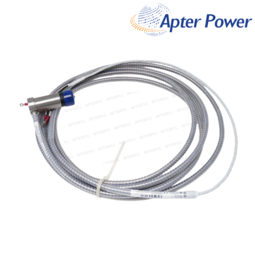


Selection
- Confirm the 5 mil range and 7.0 m total NSv chain from the loop drawing.
- Check bulkhead hole pattern, service access and CSA Division 2 marking against the enclosure design.

A 0-5 mil peak-to-peak vibration transmitter for a 7.0 m NSv system, with bulkhead mounting and CSA Division 2 approval option.
Item NO.:
990-05-70-02-01Order(MOQ):
1Goods Stock:
12Payment:
T/TLead Time:
In stockWeight:
0.44kgDimension:
7.4x4.6x10cmDescription:
990 Vibration TransmitterPrice:
AskA 0-5 mil peak-to-peak vibration transmitter for a 7.0 m NSv system, with bulkhead mounting and CSA Division 2 approval option.
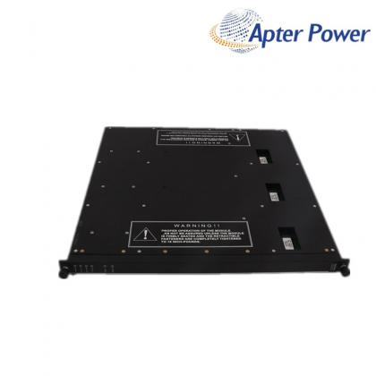
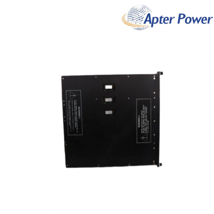
This 990 transmitter provides a simple route from a 3300 NSv proximity chain to a plant 4-20 mA vibration channel. Its buffered Prox Out connection gives maintenance a direct view of the proximity signal during setup and troubleshooting. For this loop, 990-05-70-02-01 combines the specified vibration range, system length and mounting method.
The configured range is 0-5 mil peak-to-peak, with a 7.0 m total probe-and-extension-cable path. Bulkhead screws suit panel mounting, and approval code 01 identifies the CSA Division 2 option. Those four option fields distinguish 990-05-70-02-01 from other 990 transmitter configurations.
Before energizing the loop, confirm power, mounting clearance, coaxial connections and the DCS scale. Gap the probe within range, prove the 4 mA and 20 mA points, and keep a machine-state baseline for future comparisons. Saving the 990-05-70-02-01 baseline with the machine state makes future loop diagnosis more decisive.
Add the NSv probe lead and the correct extension cable so the electrical total is 7.0 m. Use the component part numbers for this decision because routed distance alone does not identify calibrated length.
Allow room for the mounting hole, rear terminals, grounding, coaxial bend radius and access to zero, span, test and Prox Out. The bulkhead face can fit while the enclosure remains too shallow for service access.
Map 4 mA to zero vibration and 20 mA to 5 mil peak-to-peak, then verify at least one intermediate point with the approved loop-test method. This prevents a healthy transmitter from appearing incorrect in the DCS.
Set the probe inside the published 0.5 to 1.75 mm gap range and check that the output remains above the Not OK threshold. A marginal gap can drive the loop below 3.6 mA even when field wiring is intact.
The supplied unit should carry the CSA Division 2 marking that matches the project classification. The bulkhead installation method and local enclosure requirements still determine whether the completed loop is acceptable.
Compare the buffered Prox Out signal with the 4-20 mA current. A credible Prox Out signal with an incorrect DCS value points toward bulkhead wiring or scaling, while an abnormal Prox Out signal keeps attention on the 7.0 m probe chain.
Products supplied by ApterPLC are covered for 12 months under the applicable sales terms. Keep the complete unit nameplate and transaction record so the exact product can be identified during technical support.
The attached selection contains the official description, performance data, environmental limits, ordering codes and product drawings relevant to 990-05-70-02-01. Unrelated catalog pages have been removed.
|
330104-06-12-10-02-00 |
330130-035-00-00 |
330130-040-02-00 |
|
330104-06-14-50-02-00 |
330130-035-00-CN |
330130-045-00-00 |
|
330104-10-18-10-01-00 |
330130-030-01-CN |
330130-045-00-05 |
|
330104-10-20-05-02-00 |
330106-00-04-10-02-00 |
330130-040-00-00 |
|
330104-10-20-10-02-05 |
330106-05-30-05-02-00 |
330130-040-00-05 |
|
330104-12-20-10-01-00 |
330105-02-12-50-02-00 |
330130-040-01-05 |
|
330104-13-20-10-02-00 |
330106-05-30-10-02-00 |
330130-045-01-00 |
|
330104-15-23-10-02-00 |
330106-05-30-10-02-05 |
330130-045-02-05 |
|
330104-19-25-10-11-05 |
330106-05-30-15-02-00 |
330130-045-03-05 |
|
330105-02-12-05-02-00 |
330106-05-30-50-02-00 |
330130-035-01-CN |
|
330105-02-12-05-02-05 |
330130-00-05-05-02-00 |
330130-045-00-CN |
|
330105-02-12-10-02-00 |
330106-05-30-05-02-CN |
330130-045-01-CN |
|
330105-02-12-15-12-05 |
330106-05-30-10-02-CN |
330130-040-00-CN |
|
330105-02-12-15-12-CN |
330106-05-30-15-02-CN |
330130-040-02-CN |
|
330105-02-12-05-02-CN |
330106-05-30-20-02-CN |
330130-040-10-CN |
Related Tags :

SALES SUPPORT
32D floor,Guomao building,Hubin South Road,Siming District,Xiamen,Fujian,China.


Apter Power sells new and surplus products and develops channels for purchasing such products. This website has not been approved or recognized by any of the listed manufacturers or trademarks.
Apter Power is not an authorized distributor, dealer, or representative of the products displayed on this website. All product names, trademarks, brands, and logos used on this website are the property of their respective owners. The description, explanation, or sale of products with these names, trademarks, brands, and logos is for identification purposes only and is not intended to indicate any association with or authorization from any rights holder.