

Selection
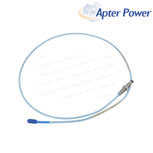
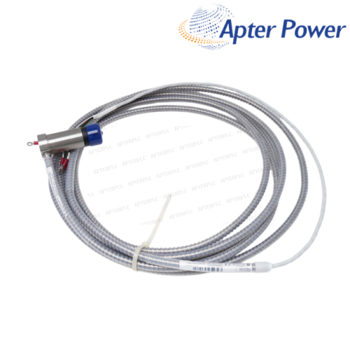
- Confirm that the existing NSv probe and cable total 7.0 m.
- Check enclosure drilling and service access for the bulkhead mount.
Item NO.:
990-05-70-02-00Order(MOQ):
1Goods Stock:
12Payment:
T/TLead Time:
In stockWeight:
0.55KGDimension:
7.8x3x6.2cmDescription:
TRANSMITTERPrice:
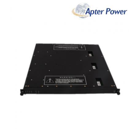
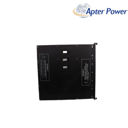
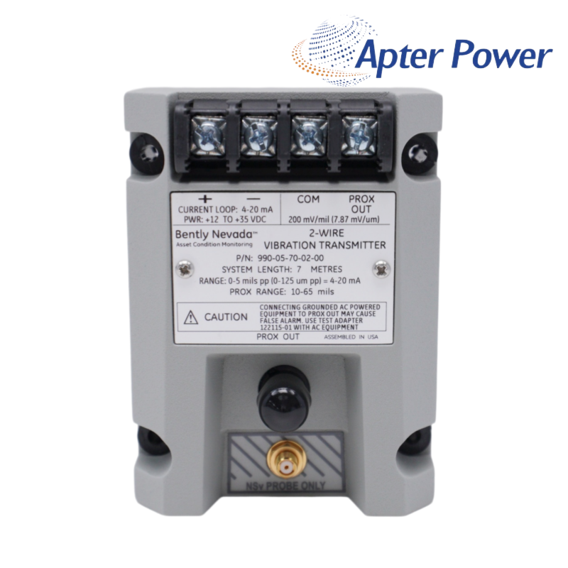
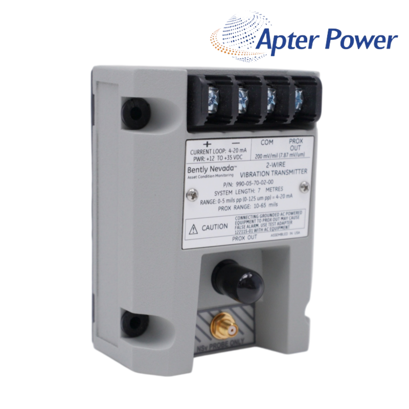
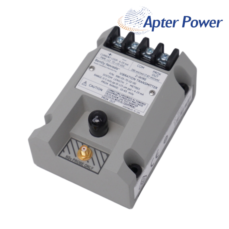
AskA 5 mil full-scale vibration transmitter for a 7.0 m NSv system with bulkhead mounting and no agency approval option.
This 990 configuration turns shaft-relative vibration into a two-wire 4–20 mA signal for a PLC or DCS. Its 7.0 m NSv system length is useful when the probe-to-transmitter route exceeds the common 5 m arrangement, while the bulkhead hardware supports enclosure-wall mounting.
The model is scaled for 0–5 mil peak-to-peak vibration, code 70 sets the probe-and-extension-cable total to 7.0 m, and code 02 selects bulkhead mounting screws. The final code 00 means no agency approval option is specified.
The 4–20 mA output is well suited to trending and general protection, but commissioning should still include probe gap and Prox Out checks. That extra step prevents a wiring or mechanical problem from being hidden behind a plausible-looking loop current.
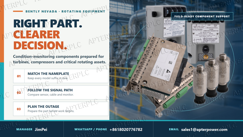
Add the probe lead and extension-cable lengths and confirm that their documented total is 7.0 m. System length is part of the calibrated signal chain, not spare cable allowance.
Confirm the mounting template, internal clearance, wire bend space, grounding plan and access to the terminals and diagnostic point.
Code 00 means no agency approval option is specified. This configuration is appropriate only where the project classification and local requirements permit it.
Check that 4–20 mA is scaled to 0–5 mil peak-to-peak and that engineering units, range and channel type match at every receiving system.
Measure supply at the transmitter, inspect loop continuity, verify probe gap and NSv connectors, then use Prox Out to narrow the fault.
Record probe model and lead length, extension-cable length, transmitter model, final gap, loop load and a stable running baseline.
Products supplied by ApterPLC are covered for 12 months under the applicable sales terms. The complete nameplate and transaction record help our team identify the exact unit when support is needed.
This Bently Nevada document covers operation, electrical specifications, wiring and ordering information for 990-05-70-02-00. It provides a practical reference for model selection, installation planning and maintenance.
|
330104-06-12-10-02-00 |
330130-035-00-00 |
330130-040-02-00 |
|
330104-06-14-50-02-00 |
330130-035-00-CN |
330130-045-00-00 |
|
330104-10-18-10-01-00 |
330130-030-01-CN |
330130-045-00-05 |
|
330104-10-20-05-02-00 |
330106-00-04-10-02-00 |
330130-040-00-00 |
|
330104-10-20-10-02-05 |
330106-05-30-05-02-00 |
330130-040-00-05 |
|
330104-12-20-10-01-00 |
330105-02-12-50-02-00 |
330130-040-01-05 |
|
330104-13-20-10-02-00 |
330106-05-30-10-02-00 |
330130-045-01-00 |
|
330104-15-23-10-02-00 |
330106-05-30-10-02-05 |
330130-045-02-05 |
|
330104-19-25-10-11-05 |
330106-05-30-15-02-00 |
330130-045-03-05 |
|
330105-02-12-05-02-00 |
330106-05-30-50-02-00 |
330130-035-01-CN |
|
330105-02-12-05-02-05 |
330130-00-05-05-02-00 |
330130-045-00-CN |
|
330105-02-12-10-02-00 |
330106-05-30-05-02-CN |
330130-045-01-CN |
|
330105-02-12-15-12-05 |
330106-05-30-10-02-CN |
330130-040-00-CN |
|
330105-02-12-15-12-CN |
330106-05-30-15-02-CN |
330130-040-02-CN |
|
330105-02-12-05-02-CN |
330106-05-30-20-02-CN |
330130-040-10-CN |
Related Tags :

SALES SUPPORT
32D floor,Guomao building,Hubin South Road,Siming District,Xiamen,Fujian,China.


Apter Power sells new and surplus products and develops channels for purchasing such products. This website has not been approved or recognized by any of the listed manufacturers or trademarks.
Apter Power is not an authorized distributor, dealer, or representative of the products displayed on this website. All product names, trademarks, brands, and logos used on this website are the property of their respective owners. The description, explanation, or sale of products with these names, trademarks, brands, and logos is for identification purposes only and is not intended to indicate any association with or authorization from any rights holder.