Item NO.:
149992-02Order(MOQ):
1Goods Stock:
30Payment:
T/TLead Time:
In stockWeight:
0.52KGDimension:
2.5x11x24cmDescription:
RELAY OUTPUT MODULEPrice:
Ask3500/33 16-Channel Relay Module · Exact-model review for engineering and procurement decisions.
|
Confirm the installed configuration before ordering
Manager JimPei · Model, nameplate and technical-document review
|
Email: sales1@apterpower.com WhatsApp: +8618020776782 |
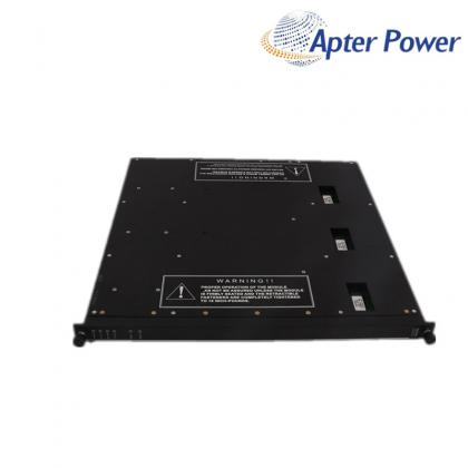
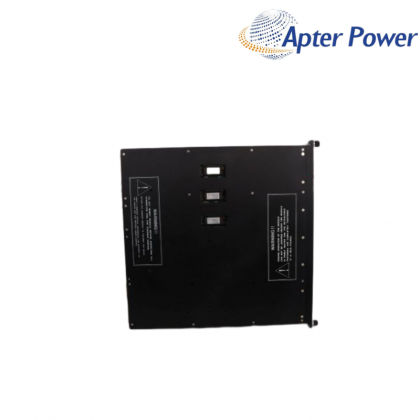
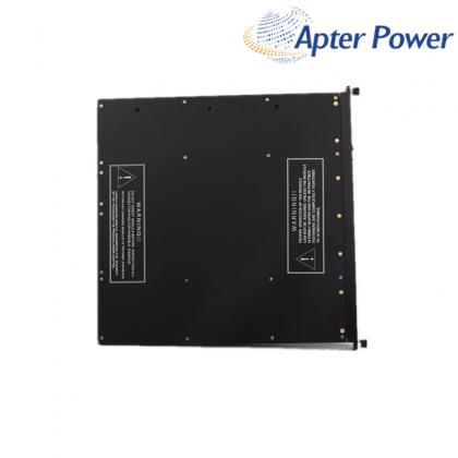
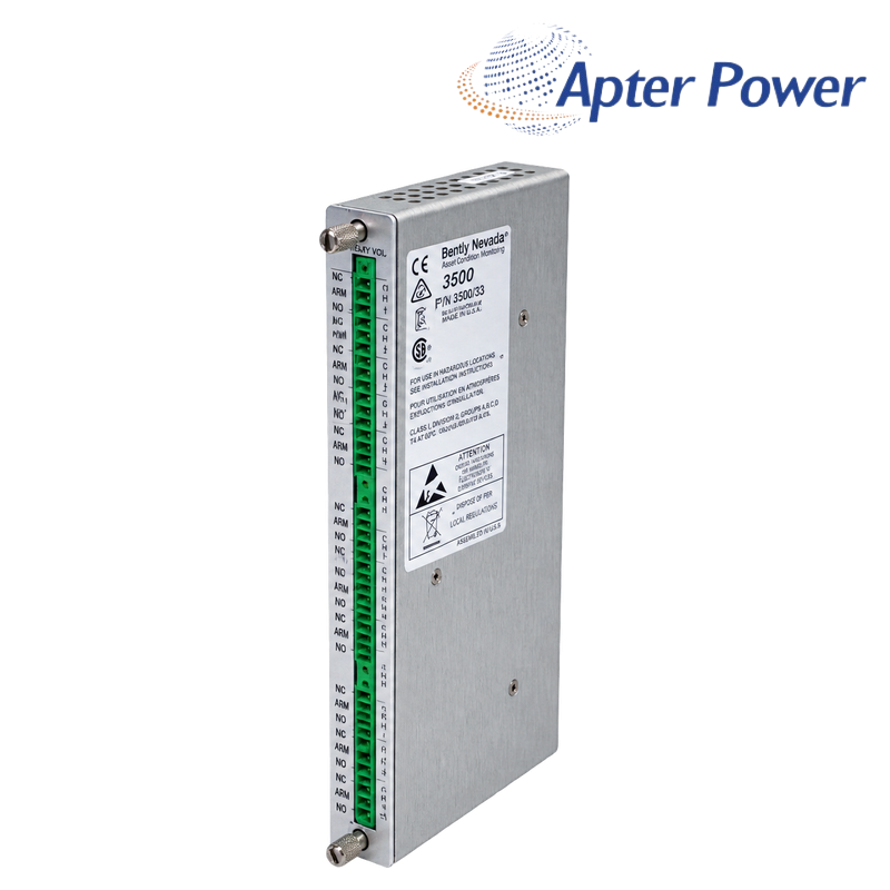
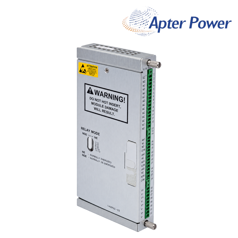
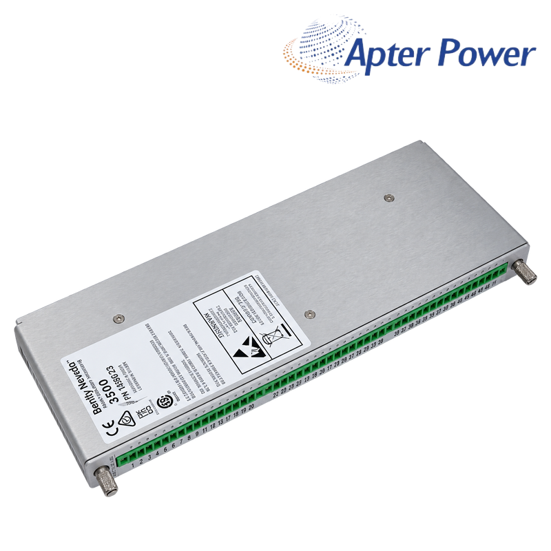
149992-02 is the manufacturer-listed 16-channel failsafe relay output module for the Bently Nevada 3500/33. Its sixteen SPDT relay outputs can be assigned voting logic that combines rack alarm states and measured variables for annunciation or control-interface duties.
149992-02 differs from the standard relay output option through its failsafe configuration. The load voltage, contact current, normally energized or normally de-energized group selection, field wiring and configured logic must all be checked before it replaces another 3500/33 rear module.
Sixteen independent outputsProvides sixteen SPDT relay channels for the associated 3500/33 module. |
Programmable voting logicAllows each relay to use AND/OR combinations of supported rack alarm and status inputs. |
Failsafe configurationSupplies the manufacturer-defined failsafe relay-output option rather than the standard relay variant. |
The manufacturer warns that inserting or removing this module while the rack is powered can damage it. Isolate power, verify absence of voltage and record the existing relay-group switch positions and terminal assignments before replacement.
| Manufacturer | Bently Nevada, a Baker Hughes business |
|---|---|
| Product family | 3500 Series |
| Associated module | 3500/33 16-Channel Relay Module |
| I/O identity | 16-Channel Failsafe Relay Output Module |
| Relay outputs | 16 |
| Contact arrangement | Single-pole double-throw (SPDT) |
| Relay construction | Epoxy-sealed |
| Operating-mode selection | Four groups of four relays; normally energized or normally de-energized |
| Logic configuration | AND/OR voting logic through 3500 Rack Configuration Software |
| Failsafe-output voltage boundary | 30 Vdc maximum |
| Silver-contact minimum load | 100 mA at 5 Vdc |
| Software baseline | 3500 Rack Configuration Software 3.3 or later |
Commercial packing weight and packed dimensions remain in the page logistics fields unless the manufacturer publishes model-specific packing data.
Configuration & ProgrammingEach relay can combine supported alarm or status inputs through programmed AND/OR logic. Preserve the existing configuration and verify every output against the approved cause-and-effect before return to service. |
Diagnostics & ProtectionA front-panel relay indication does not prove that the field load has operated. Diagnose the output in order: configured logic, group mode, relay contact state, terminal wiring and external load power. |
Relay-circuit matching: For quotation and replacement, provide the front-module and rear-I/O numbers, contact load, supply voltage, normally energized/de-energized selection, software version and a photograph of the terminal wiring.
Not without a circuit review. This is the failsafe output version, so confirm the installed rear-I/O number, field voltage and current, contact use and normally energized/de-energized selection before substituting it.
The four-relay group switch positions and the downloaded voting logic both affect the final contact state. Isolate the field action, compare the preserved switch settings and approved cause-and-effect, then correct the mismatch before returning the output to service.
Use 3500 Rack Configuration Software 3.3 or later, back up the approved rack project and verify every relay assignment against the cause-and-effect. Stop if the available project or software cannot reproduce the installed logic.
Check the selected group mode, COM/NO/NC terminal assignment, external load supply and contact load before changing the logic. De-energize the field circuit before moving conductors, and stop if the load is outside the failsafe-output rating.
No. The manufacturer warns that live insertion or removal can damage the module. Isolate and verify rack power, record the terminal wiring and switch positions, and only then remove or install the rear I/O.
Send the front-module and rear-I/O nameplates, relay load voltage and current, group-mode settings, rack configuration-software version, required approvals and clear terminal photographs.
Product identity and technical statements were checked against 3500/33 16-Channel Relay Module Datasheet, document 162301 Rev. AC. Verify the complete installed nameplate, revision, companion components and project drawing before commissioning.
Apter's 1 Year Warranty
Apter provides a 1-year warranty on every item we sell.
Our free 1-year warranty makes every Apter purchase a dependable, reliable investment in your company's future.
Apter sells industrial automation parts including new and discontinued products, and purchases such featured products through independent channels. Apter is not an authorized distributor, dealer or representative of the products featured on this site. All product names/product images, trademarks, brands and logos used on this website are the property of their respective owners. Product descriptions, depictions or sales with these names, images, trademarks, brands and logos are for identification purposes only and do not imply any affiliation or authorization to any rights holder.
Related Tags :

SALES SUPPORT
32D floor,Guomao building,Hubin South Road,Siming District,Xiamen,Fujian,China.


Apter Power sells new and surplus products and develops channels for purchasing such products. This website has not been approved or recognized by any of the listed manufacturers or trademarks.
Apter Power is not an authorized distributor, dealer, or representative of the products displayed on this website. All product names, trademarks, brands, and logos used on this website are the property of their respective owners. The description, explanation, or sale of products with these names, trademarks, brands, and logos is for identification purposes only and is not intended to indicate any association with or authorization from any rights holder.